USB power render, front
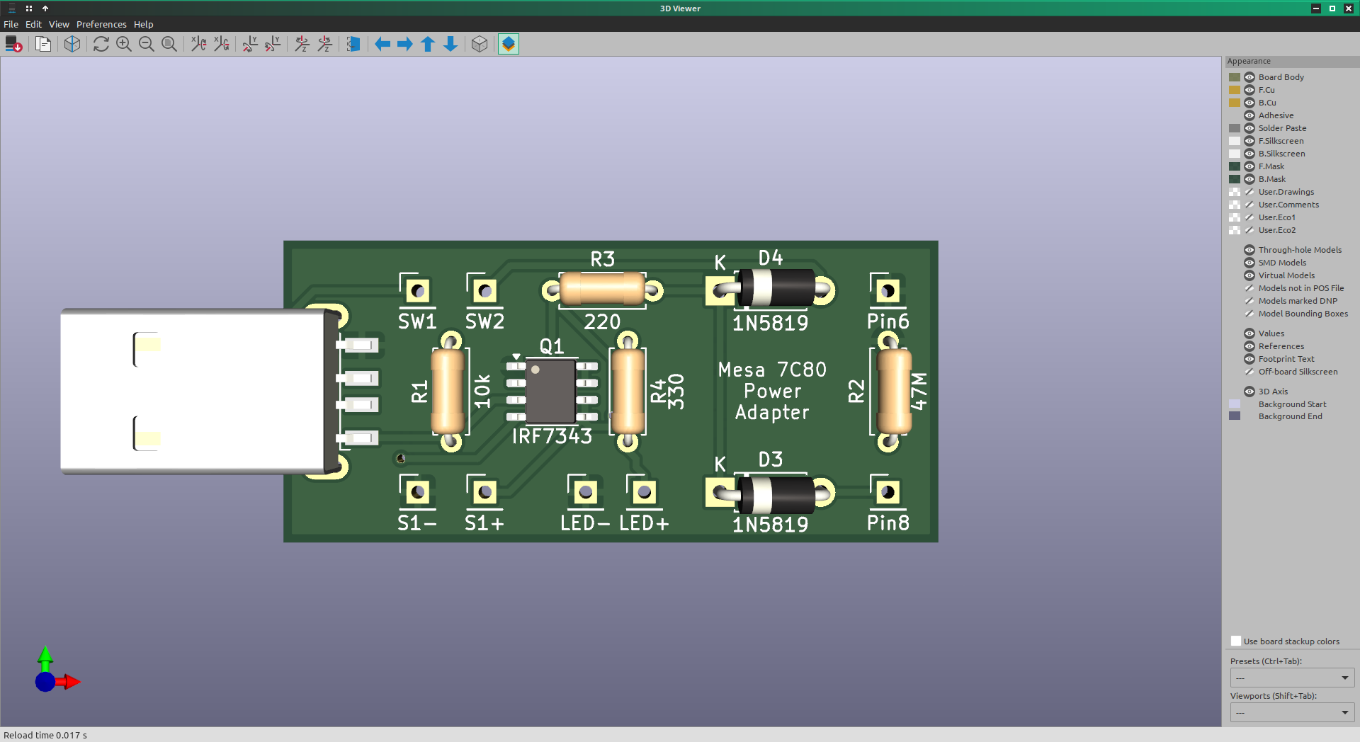
SW1&2 go to a momentary "power on" switch near display. LED1&2 are the "power on" indicator. S1+/- go to the SSR. Pin6/8 are spliced into the Rpi GPIO.
SW1&2 go to a momentary "power on" switch near display. LED1&2 are the "power on" indicator. S1+/- go to the SSR. Pin6/8 are spliced into the Rpi GPIO.